The PowerFlex 70 is a high-performance adjustable frequency AC drive designed for industrial automation, offering versatile control for motor applications․ It ensures energy efficiency, precise speed regulation, and robust operation, making it a reliable solution for industrial processes․ The drive is user-friendly, with advanced features and a compact design, suitable for various applications requiring precise motor control․
1․1 Overview and Applications
The PowerFlex 70 is a versatile AC drive designed for industrial automation, offering precise motor control and energy efficiency․ It is widely used in applications like pumps, fans, conveyors, and machinery requiring variable speed operation․ The drive supports both open-loop and closed-loop control, making it suitable for diverse industrial processes․ Its compact design and user-friendly interface allow easy integration into existing systems․ With adjustable frequency control, the PowerFlex 70 ensures smooth operation, reduced wear on machinery, and optimal performance in various environments․ It is ideal for applications requiring reliable, efficient, and adaptable motor control solutions․

Safety Precautions in Wiring
Always ensure the power is off before wiring․ Wear protective gear and avoid hot wiring․ Follow the manual strictly to prevent hazards and ensure safe installation․
2․1 Key Safety Considerations
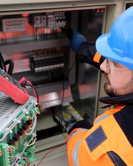
Ensure the power supply is disconnected before starting any wiring․ Always wear protective gear, including gloves and safety glasses․ Follow the manufacturer’s guidelines strictly to avoid electrical hazards․ Properly ground the system to prevent shocks and ensure safe operation․ Never bypass safety features or override protective circuits․ Use appropriate tools and avoid hot wiring․ Regularly inspect cables and connections for damage․ Keep the work area clear of flammable materials․ Adhere to local electrical codes and standards․ If unsure, consult a qualified professional to ensure compliance and safety․
2․2 Importance of Proper Wiring Practices
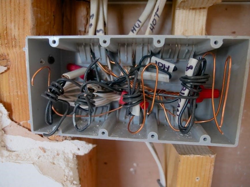
Proper wiring practices are critical to ensure the safe and reliable operation of the PowerFlex 70․ Correct wiring minimizes the risk of electrical hazards, reduces interference, and prevents damage to the drive and connected equipment․ It also ensures compliance with safety standards and manufacturer guidelines․ Improper wiring can lead to malfunctions, overheating, or even complete system failure․ Always follow the recommended wiring diagrams and use appropriate cables rated for the voltage and current․ Regularly inspect connections to prevent wear and tear․ Proper wiring practices not only enhance performance but also protect personnel and equipment from potential risks․ Adherence is essential for long-term reliability․
Wiring Requirements for PowerFlex 70
The PowerFlex 70 requires precise wiring to ensure optimal performance and safety․ Proper voltage, current, and essential components must be correctly connected to meet specifications and prevent faults․
3․1 Voltage and Current Ratings
The PowerFlex 70 operates within specific voltage and current ranges to ensure reliable performance․ It supports standard industrial voltages, such as 208V, 240V, 380V, and 480V, depending on the model․ Proper wiring must match the drive’s rated current to avoid overheating or damage․ Incorrect voltage or current configurations can lead to malfunctions or safety hazards․ Always refer to the product manual for precise ratings and guidelines to ensure compatibility with your motor and power supply․ Correct voltage and current settings are crucial for optimal operation and longevity of the drive․
3․2 Essential Components for Wiring
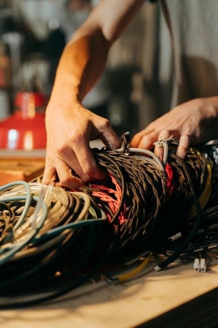
The PowerFlex 70 wiring setup requires several key components to ensure proper electrical connections․ These include a motor contactor, circuit breaker, and fuses for overcurrent protection․ Shielded cables are recommended for power and control connections to minimize electromagnetic interference․ Additionally, terminal blocks and quick-connect tabs facilitate secure wiring․ A grounding conductor is essential to prevent noise and ensure safety․ Proper sizing of all components, based on the drive’s current rating, is critical to avoid overheating and maintain system reliability․ Using the correct materials and connectors helps prevent electrical noise and ensures smooth operation of the drive system․
3․3 Understanding Wiring Diagrams
Wiring diagrams for the PowerFlex 70 are essential for proper installation and troubleshooting․ They provide a visual representation of electrical connections, ensuring components are linked correctly․ Standard symbols represent resistors, capacitors, and connectors, while color-coded lines differentiate between power, ground, and control signals․ The diagram outlines the drive’s input/output terminals, motor connections, and control circuits․ Always refer to the manufacturer’s manual for accurate interpretation․ Pay attention to grounding points and shielding requirements to minimize noise․ Verify connections match the diagram to avoid faults․ Proper understanding ensures safe and efficient operation of the PowerFlex 70 drive system․

Step-by-Step Installation Guide
The PowerFlex 70 installation involves mounting, wiring, and configuring the drive․ Follow manual instructions for secure mounting and precise wiring connections to ensure optimal performance and safety․
4․1 Pre-installation Checks
Before installing the PowerFlex 70, ensure the site meets all safety and environmental requirements․ Verify voltage and current ratings match the drive specifications․ Inspect the wiring for damage or wear․ Ensure proper grounding for noise reduction and safety․ Check the motor compatibility with the drive’s output․ Review the manual for specific installation guidelines․ Ensure all necessary tools and components are available․ Perform a visual inspection of the drive and accessories for any signs of damage․ Familiarize yourself with the control circuit requirements and ensure all safety precautions are in place to avoid potential hazards during installation․
4․2 Mounting and Connecting the Drive
Mount the PowerFlex 70 on a flat, sturdy surface using the provided mounting hardware․ Ensure proper ventilation to maintain operating temperatures․ Connect the motor and input power cables securely to the designated terminals, following the wiring diagram․ Verify all connections for tightness and correct polarity․ Install any additional components like fuses or circuit breakers as per specifications․ Use the control terminal block for input/output signals, ensuring correct wiring for start/stop and speed reference controls․ Double-check all connections before powering up to prevent damage or malfunctions․ Refer to the manual for detailed diagrams and specific wiring instructions to ensure a safe and proper installation․

Configuring Control Circuits
Configure control circuits for start/stop and speed reference using digital inputs․ Ensure proper wiring for forward/reverse operation and speed potentiometer connections․ Refer to the manual for diagrams and settings to optimize performance and safety․
5․1 Setting Up Start/Stop Controls
To configure start/stop controls for the PowerFlex 70, use a 3-wire control circuit․ Wire the start and stop commands to digital inputs, ensuring proper connections for forward and reverse operations․ Use Byte Offset 0, Bit 0 for the STOP command and another bit for START․ Verify wiring integrity and ensure the control circuit matches the drive’s settings․ Refer to the manual for diagrams and parameter configurations․ Always follow safety protocols when handling electrical components․ Test the controls after setup to ensure proper functionality and safe operation of the drive․
5․2 Configuring Speed Reference
To configure the speed reference for the PowerFlex 70, connect the speed reference signal to the drive’s analog input terminals (AI1 or AI2)․ Use a 0-10V or 4-20mA signal, depending on the application․ Ensure proper wiring, using shielded cables to minimize noise․ Program the drive to recognize the input type by setting the correct parameters․ Adjust the scaling to match the desired speed range․ Test the configuration by varying the reference signal and verifying the motor speed response․ This setup ensures precise speed control and smooth operation of the connected motor․ Always refer to the manual for specific parameter settings and safety guidelines․

Troubleshooting Common Wiring Issues
Check for loose connections, short circuits, or improper shielding․ Verify wiring against diagrams to ensure correct terminal assignments․ Address faults like unexpected stoppages or error codes promptly for reliable operation․
6․1 Identifying Faults
Identifying faults in PowerFlex 70 wiring involves checking for error codes, unusual LED indicators, or unexpected drive behavior․ Common issues include short circuits, loose connections, or incorrect wiring configurations․ Fault codes like Port 5 Adaptor FLT75 indicate specific problems․ Use diagnostic tools or consult the manual to interpret error messages․ Verify wiring against diagrams to ensure correct terminal assignments․ Physical inspections can reveal damaged or corroded wires․ Addressing these issues promptly prevents further damage and ensures reliable operation․ Regular maintenance and checks help mitigate potential faults before they escalate․ Always refer to the manual for detailed troubleshooting guidance․
6․2 Diagnostic Techniques
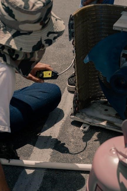
Diagnostic techniques for PowerFlex 70 wiring involve systematic checks to identify and resolve issues․ Start by reviewing error codes and LED indicators on the drive, which provide insights into specific faults․ Use the drive’s built-in diagnostic tools or software to analyze performance data․ Check wiring diagrams to ensure connections match the recommended configuration․ Inspect physical connections for damage, corrosion, or loose terminals․ Test voltage levels at key points to verify power supply integrity․ For recurring issues like Port 5 Adaptor FLT75 faults, consult the manual or reset the drive as needed․ Regular diagnostic checks help prevent downtime and ensure smooth operation․
Maintenance and Upkeep
Regular maintenance ensures optimal performance and longevity of the PowerFlex 70․ Schedule routine inspections of wiring and connections, clean dust from components, and verify firmware updates․ Always refer to the manual for specific guidelines to maintain efficiency and safety․
7․1 Routine Checks
Perform routine checks to ensure the PowerFlex 70 operates efficiently․ Verify all connections are secure, and inspect wiring for signs of wear or damage․ Check for dust buildup on components and clean as needed․ Ensure the drive is mounted securely to prevent vibration․ Validate firmware is up-to-date for optimal performance․ Regularly test emergency stop circuits to confirm functionality․ Monitor drive temperatures and ensure proper cooling․ Review system logs for error codes and address issues promptly․ These checks help prevent unexpected downtime and maintain reliable operation․
7․2 Best Practices
Adhere to best practices to optimize the performance and longevity of your PowerFlex 70 installation․ Always follow the manufacturer’s guidelines for wiring and configuration to ensure reliability․ Use high-quality components and tools to maintain system integrity․ Regularly consult the latest user manuals for updates or changes in recommendations․ Keep wiring organized and labeled for easy identification and future maintenance․ Schedule periodic inspections to identify potential issues early․ Train personnel on proper operation and troubleshooting to minimize downtime․ Document system configurations for reference and future upgrades․ By following these practices, you ensure a safe, efficient, and durable installation․
The PowerFlex 70 wiring manual provides a comprehensive guide for safe and efficient installation․ Proper practices ensure reliability and longevity, while adherence to safety guidelines minimizes risks․